Pages

Rabu, 23 Oktober 2013

Class Diagram

      A class diagram is an illustration of the relationships and source code dependencies among classes in the Unified Modeling Language (UML). In this context, a class defines the methods and variables in an object, which is a specific entity in a program or the unit of code representing that entity.
In a class diagram, the classes are arranged in groups that share common characteristics. A class diagram resembles a flowchart in which classes are portrayed as boxes, each box having three rectangles inside. The top rectangle contains the name of the class; the middle rectangle contains the attributes of the class; the lower rectangle contains the methods, also called operations, of the class. Lines, which may have arrows at one or both ends, connect the boxes. These lines define the relationships, also called associations, between the classes.


So the purpose of the class diagram can be summarized as:
- Analysis and design of the static view of an application.
- Describe responsibilities of a system.
- Base for component and deployment diagrams.
- Forward and reverse engineering.


      Class diagrams are the most popular UML diagrams used for construction of software applications. So it is very important to learn the drawing procedure of class diagram. Class diagrams have lot of properties to consider while drawing but here the diagram will be considered from a top level view. Class diagram is basically a graphical representation of the static view of the system and represents different aspects of the application. So a collection of class diagrams represent the whole system.


Class
 A class represents an entity of a given system that provides an encapsulated implementation of certain functionality of a given entity. These are exposed by the class to other classes as methods. Apart from business functionality, a class also has properties that reflect unique features of a class. The properties of a class are called as attributes. The UML representation of a class is a rectangle containing three compartments stacked vertically

Association
An association represents a relationship between two classes. An association indicates that objects of one class have a relationship with objects of another class, in which this connection has a specifically defined meaning.


This is the example of class diagram about blog system:


Mengelola Comment
(addComment, viewComment, replyComment)
Attribute     : isi_comment, tgl_comment, panjang_isiComment, email
Operation   : set_isiComment, get_isiComment, set_tglComment, get_tglComment

Mengelola Profil
(addNewProfil, editProfil)
Attribute     : id_profil, nama_profil, email
Operation   : set_idProfil, set_namaAdmin, get_namaAdmin

Mengelola Template
(editHtml, cadangkan/pulihkan)
Attribute     : isi_html
Operation   : set_isiHtml, get_isiHtml

Mengelola Posting
(inputNewPosting, editPosting, deletePosting, viewPosting)
Attribute     : isi_posting, tgl_posting, panjang_isiPosting
Operation   : set_isiPosting, get_isiPosting, set_tglPosting, get_tglPosting

Mengelola Layout
(addGadget, editGadget, deleteGadget)
Attribute     : isi_gadget
Operation   : set_isiGadget, get_isiGadget

Monetize Blog
(approveIklan)
Attribute     : id_iklan, email, isi_iklan, tgl_iklan
Operation   : get_idIklan, set_isiIklan, get_isiIklan, set_tglIklan, get_tglIklan

Senin, 14 Oktober 2013

Use Case Diagram

A use case diagram is a graphic depiction of the interactions between system elements. A use case is a methodology used in system analysis to identify, clarify, and organize system requirements. In this context, the term system refers to something being developed or operated, such as a mail-order product sales and service Web site. Use case diagrams are employed in UML (Unified Modeling Language), a standard notation for the modeling of real-world objects and systems.


A use case diagram contains four components.
  •           The boundary, which defines the system of interest in relation to the world around it.
  •           The actors, usually individuals involved with the system defined according to their roles.
  •           The use cases, which are the specific roles played by the actors within and around the system.
  •           The relationships between and among the actors and the use cases.  


We can use the following elements in use case diagrams :

Actor : An actor represents a role that an outsider takes on when interacting with the business system. For instance, an actor can be a customer, a business partner, a supplier, or another business system.

Association : An association is the relationship between an actor and a business use case. It indicates that an actor can use a certain functionality of the business system - the business use case.

Use Case : A business use case describes the interaction between an actor and a business system, meaning it describes the functionality of the business system.

Include : The include relationship is a relationship between two business use cases that signifies that the business use case on the side to which the arrow points is included in the use case on the other side of the arrow. This means that for one functionality that the business system provides, another functionality of the business system is accessed.

Generalization : A generalization relationship is also a parent-child relationship between use cases. The child use case in the generalization relationship has the underlying business process meaning, but is an enhancement of the parent use case. In a use case diagram, generalization is shown as a directed arrow with a triangle arrowhead. The child use case is connected at the base of the arrow. The tip of the arrow is connected to the parent use case.

Extends : An extends shows the relationships between use cases. Relationship between use case A and use case B indicates that an instance of use case B may include (subject to specified in the extension) the behavior specified by A. An 'extends' relationship between use cases is depicted with a directed arrow having a dotted shaft. The tip of arrowhead points to the parent use case and the child use case is connected at the base of the arrow. For example, validating the user for a system. A invalid password is extension of validating password use case.


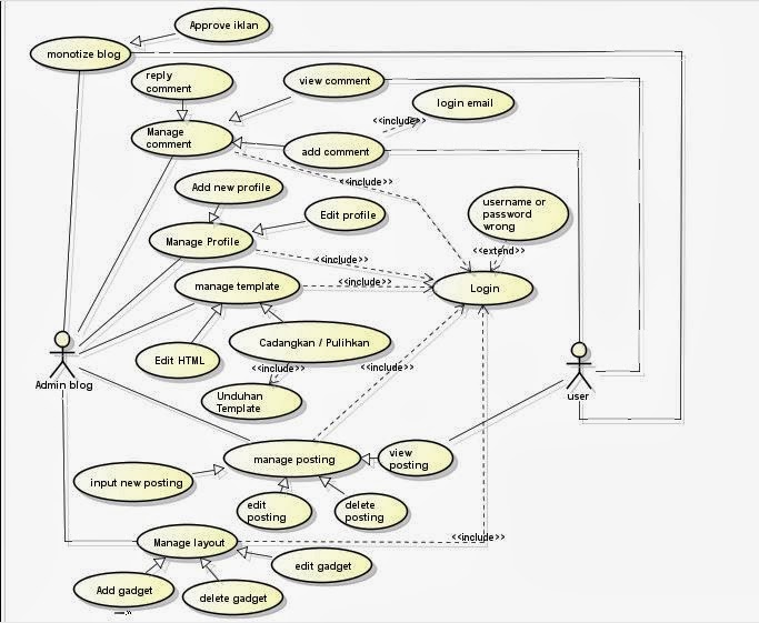
Here’s simple example of use case diagram about blog system :


Monetize blog
Here you can add ads to your blog. When you sign up with one of these services, you’re given code to add to your site that will link to whatever content or services those companies are currently promoting. Other sponsored ads come from individual companies and promote only that company and its products or services. After that you can put these ads in the section you want.

Manage comment
You can see the existing comments and can reply a comment from the visitors. Visitors can also see the comments on the blog, as well as be able give a comment only after login using their own email visitors.

Manage profile
You can add a new profile on the blog if you have already registered in the email. If you are logged into your emails, then you have to create a new blog. Here you can also edit your profile.

Manage template
Here you can change the background by using a basic template and then customize the background, layout, colors, fonts, etc. But first you have to download a template for a blog on the internet.

Manage posting
You can add and publish your new post, and can also edit and delete existing blog posts. You can see your own post by clicking on the blog look. Visitors can also see and visit our blog for free, whenever and wherever.

Manage layout
The manage layout you can add, delete and edit gadget in your blog. or you can click and drag to rearrange the gadgets.